Skip to content

Calibration Process

Calibration of the FoveaCam Duo system proceeds in three stages.

Intrinsic Calibration of the Wide-Angle Camera

The central wide-angle camera serves as the angular reference for the entire system. We perform a standard intrinsic calibration using a checkerboard pattern to obtain the camera matrix K and distortion coefficients, from which we derive a pixel-to-angle mapping. Specifically, for any pixel coordinate (px,py) in the wide-angle image, we compute the corresponding ray direction (αx,αy) relative to the camera's optical axis. This mapping is used in the subsequent extrinsic calibration stage to establish ground-truth angular poses for all three cameras.

Extrinsic Calibration: MEMS Voltage to Pointing Angle

The goal of this step is to establish a mapping from mirror control voltages (vx,vy) to the angular direction (αx,αy) of the optical axis of each foveated telephoto camera. To achieve this, we mount the camera system on a custom-designed pan-tilt platform and sweep it through predefined angular poses.

(a) (c) (b) L C R d d D
Figure 1

Extrinsic calibration setup. (a) The FoveaCam Duo system is mounted on a pan-tilt platform that sweeps the assembly through a grid of xy angles; (b) Three ArUco markers, one per camera, are placed at distance D and spaced by the stereo baseline d; (c) Geometric diagram showing the angular error δθ=|θCθL||θCθR| introduced by the lateral offset.

For each of the three cameras in our system, we place an ArUco marker with a distinct ID for the camera to track. The markers are spaced out and aligned exactly according to the physical layout. This alignment ensures the angular subtense from each camera to its corresponding marker remains approximately constant across the steering range. The angular error δθ can be quantified as:

δθ=arctanddcos(θ)D±dsin(θ)

Given a sufficiently large distance Dd, the angular error δθ becomes negligible.

During calibration, we sweep the MEMS mirror through a 9×9 grid of voltage values (vx,vy). At each position, the wide-angle center camera observes its own ArUco marker and, using the intrinsic pixel-to-angle mapping, determines the ground-truth angular position (αx,αy). Simultaneously, each foveated camera tracks its dedicated marker with a PID controller to keep the marker centered in its field of view.

Using the voltage readings from both drivers once the markers are stabilized at center, we associate each voltage pair (vx,vy) with the angular direction (αx,αy) via a 3rd-order polynomial regression model:

[vxvy]=K[αx3αy3αx2αyαxαy21.0αx3αy3αx2αyαxαy21.0][αxαy]=T[vx3vy3vx2vyvxvy21.0vx3vy3vx2vyvxvy21.0]

where K and T are 2×10 coefficient matrices for the forward and inverse mappings, respectively. Each row multiplies the 10-element cubic polynomial basis [αx3,αy3,αx2αy,αxαy2,,1].

Measurement (Ground T ruth) [ V olt / Angle ] Prediction (Regression)
Figure 2
Extrinsic calibration regression results for the left and right foveated cameras. Each panel plots raw measurements "○" against reprojected points from the polynomial regression model, confirming sub-pixel reprojection accuracy.

Foveated Image Rectification via Homography

Images captured through the MEMS-steered telephoto optics exhibit an affine-type geometric distortion that varies with the mirror steering angle. To enable standard stereo algorithms, we must project these distorted foveated images into a canonical pinhole camera model suitable for parallel stereo geometry.
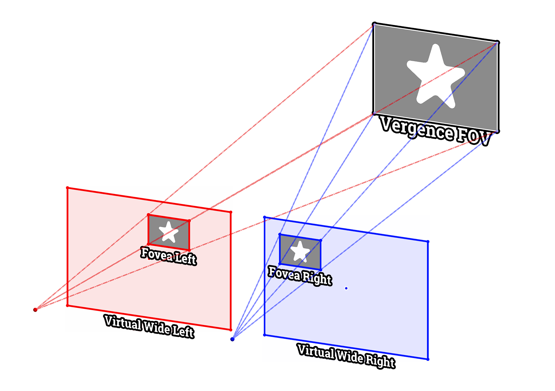
Virtual pinhole projection model
Figure 3

Virtual pinhole projection model for foveated image rectification. The MEMS-steered telephoto camera (fovea) captures images with angle-dependent affine distortion. We define a virtual pinhole camera whose optical axis is parallel to the wide-angle camera and whose focal length matches the telephoto lens. A homography H(αx,αy) projects distorted foveated image onto the virtual pinhole frame, producing a rectified image suitable for standard parallel stereo matching.

We define a virtual pinhole camera for each foveated camera with the following properties:

  1. It has the same focal length as the physical telephoto camera, and
  2. Its optical axis is parallel to that of the wide-angle camera, analogous to a classical rectified parallel stereo configuration.

This virtual camera represents where pixels would appear if the telephoto camera were a perfect pinhole camera rigidly mounted with its optical axis aligned to the system's forward direction.

To compute the rectification, we exploit the ArUco markers tracked during the extrinsic calibration stage. For each calibration sample at mirror angles (αx,αy), we extract the internal corner features of the detected ArUco markers in the foveated image. Using the known marker geometry and the calibrated pixel-to-angle mapping of the wide-angle camera, we compute the expected locations of these corners in the virtual pinhole image plane. We then compute a homography matrix H(αx,αy) that maps pixel coordinates from the distorted foveated image to the rectified virtual pinhole image for each sample point. In this computation, we assume that the telephoto lenses do not introduce significant nonlinear (e.g., radial) distortion, so a projective transformation (homography) is sufficient.

Since the homography varies continuously with the mirror steering angle, we require a compact parametric model. We fit each of the nine entries Hij of the 3×3 homography matrix as a polynomial function of the steering angles (αx,αy):

Hij(αx,αy)=m,ncmn(ij)αxmαyn

where the summation runs over polynomial basis terms up to a chosen degree. Crucially, the inclusion of cross-terms αxmαyn with both m>0 and n>0 is essential to capture the x-y coupling inherent in the MEMS mirror's two-axis steering, unlike axis-separable models that treat each axis independently. We verified that a 3rd-order polynomial (i.e., m+n3) yields accurate rectification across the entire actuation range.

At runtime, given mirror steering angle (αx,αy), we evaluate the polynomial for all nine entries to assemble H(αx,αy) and apply the resulting homography to warp the captured foveated image into the rectified virtual pinhole frame. The left and right rectified images then form a standard parallel stereo pair suitable for disparity computation and triangulation.


Figure 4

Homography rectification on the foveated stereo pair. Top: raw images from the left and right foveated cameras and their red-blue anaglyph difference. The anaglyph reveals severe misalignment. Bottom: after applying the angle-dependent homography H(αx,αy), the rectified anaglyph shows that the left and right images are now well-aligned, with residual red-blue separation visible only on the foreground Statue of Liberty model due to its true stereo disparity.